Module Mounting: Be careful of the exact version of the module. On some models we have incorporated circuitry that has pins sticking through to the bottom side of the board. If so, be sure these pins do not short to the underlying circuitry or mounting bracket. If double-sided tape is used to mount the module, be sure it's not under so much pressure that it will be pulled free some weeks or months after you've re-assembled everything. Use a hot glue gun to add some extra strength to it.
RCA Jack Mounting: You might consider making a 5/16" hole and using the extra 1/16" to be able to de-bur the edges of the hole. The metal of the RCA jack must NOT make contact with the casing of the player. Be sure the plastic washers are arranged properly to isolate it. The center pin of the RCA jack carries the AC-3 RF signal and the little washer with a tab sticking out to the side is where circuit ground attaches. The circuit ground DOES attach to the chassis ground (case of the player), but ONLY through the capacitor. One leg of the cap attaches to the ground leg of the RCA jack, and the other to any convenient screw attached to the case.
Coax: Coax wire is the supplied wire that looks like very fine cable-TV wire. It has a center conductor designed to carry signal and an outer shielding of braided wire to keep out any stray interference. The outer shielding generally attaches to circuit ground to aid it in blocking stray RF signals. Stripping the coax is difficult, and believe it or not a sharper knife is better. I use a nice sharp exacto knife. The center conductor has plastic around it, then the braided metal shielding, then an outer plastic coating.
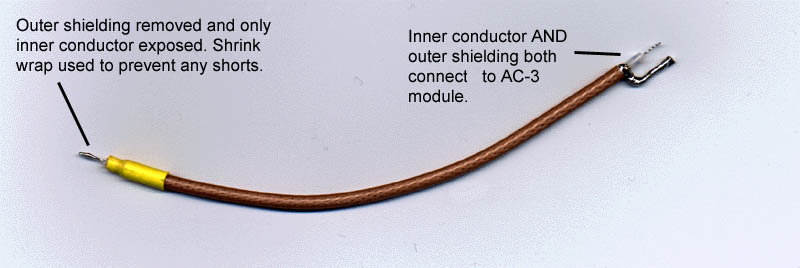
RF Pickup point on the player circuit board: Cut about 3/4" from the end all the way around going ONLY through the outer plastic coating, and the braided metal shielding. As soon as you feel the knife penetrate the metal braid, ease up the pressure and turn the wire another 1/4" turn. Pull off the braided metal outer shielding leaving the inner plastic and center conductor. Cut the plastic shielding off leaving about 1/8" between it and where the braided shielding ended. Use some shrinkwrap or electrical tape to insure that any stray wires from the braided ground/shielding do not touch any components on the players circuit board! Click Here for a picture of the coax wire cut, stripped, and tinned for connection to the AC-3 module's input and point inside the player where RF audio is tapped.
All other ends: Cut off the outer plastic shielding only, about 1" from the wire end. Peel it off and unbraid the remaining shielding and twist it back together on one side of the wire. Again, cut off the inner plastic shielding with about 1/8" separating the center conductor from the braided ground shield.
Cut the center conductor until only about 1/4" of it is exposed beyond the plastic shielding. Bend the braided ground around so that it meets exactly where it should on the module, or on the RCA jack. After it's cut to the correct length and aligned exactly the way it should be, tin both with solder very good. Tin all exposed braided ground to add strength to it to help keep the coax stable after attachment.